Introduction

LSU's Tangible Visualization Lab (TangViz) conducts research on human-computer interaction and tangible interfaces. The general definition of a token is an object that serves as a visible or tangible representation of something intangible, such as a fact, quality, or feeling. The TangViz lab 3D-prints circular tokens made of a theromplastic for interaction with digital posters. The poster displays on a 4k screen and users interact through controls on a Windows touchscreen tablet. Placing a token on the tablet turns that token into a control which users can use as input by turning it like a knob. My role in this research was to design and construct a prototype for a different type of token, one which would not require a tablet to detect rotation, and would communicate wirelessly with the computer running the poster.
Part Selection and Design
The prototype needed to be small enough to comfortably handle while maintaining the same circular shape as past tokens. In addition to being able to determine its heading and connect wirelessly, the token would also provide feedback to the user through a circular matrix of LEDs, provide acceleration data, and detect the color of the surface below it. Budget and time constraints make building a dedicated printed circuit board with customized hardware difficult to accomplish. However, a few off-the-shelf components and a prototyping board can still make an adequate prototype within these constraints. The chosen parts are listed below:
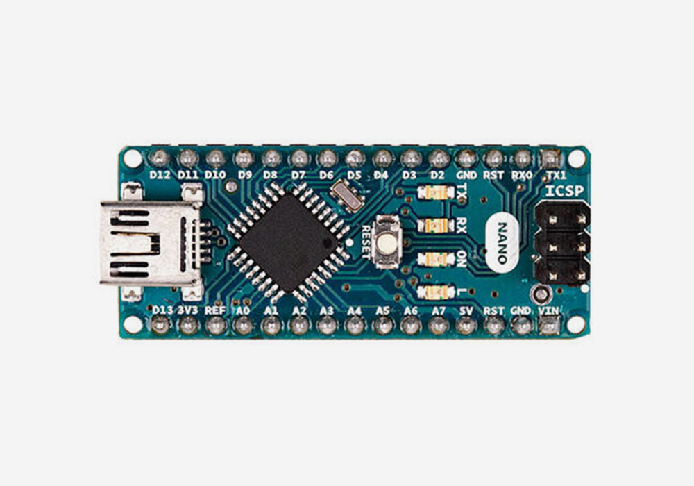 |
Arduino Micro - A small microcontroller development board. Its size makes it perfect for this project, and an integrated USB port makes programming simpler and eliminates the need for serial to USB FTDI adapters. |
 |
24 x 5050 RGB LED ring with integrated drivers - A ring of individually addressable LEDs (or neopixels) that can be set and dimmed programmatically. Each LED can draw a current of about 20mA, and each neopixel has a red, green, and blue LED, for a total maximum current of 1.44A. The power supply will need to be able to handle this in addition to the relatively nominal current draw of the other components. |
 |
LSM303 Accelerometer/Magnetometer - A combination accelerometer and compass that communicates using I2C. It provides data for acceleration in the X, Y, and Z directions, and microTesla readings in the X and Y directions which can be used to calculate a compass heading with an accuracy of about two degrees after filtering. |
 |
Bluefruit LE Module - A class 2 low energy bluetooth module that commumicates with the microcontroller using UART. |
 |
Capacitive Touch Sensor - A touch sensor in the center of the LED ring, used as a multipurpose button. It outputs a HIGH when pressed and LOW otherwise, and only needs one digital pin from the microcontroller. An on board LED illuminates when the sensor is pressed, but can also be controlled programmatically. |
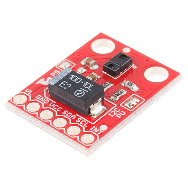 |
APDS-9960 RGB/Gesture Sensor - A combination rgb and gesture sensor that can measure ambient light and colors, and detect proximity and gestures. This sensor connects to the bottom of the token and communicates with the microcontroller using I2C. It is the only component that does not run off the 5V charger output, instead powered directly from the 3.3V microcontroller output. |
 |
2500mA Lithium Ion Polymer Battery - A high capacity lipo battery with a 2-pin JST connector. It is the highest capacity battery from this seller that can fit at the bottom of the token, and is capable of delivering a 2C discharge current (5A), which is more than sufficient for powering the token. |
 |
Powerboost 1000C Lipo Battery Charger - A small circuit board, compatible with the selected battery and capable of simulaniously charging and providing a boost from the ~3.7V battery voltage to the 5V needed to power the token. It can provide a maximum output current of 2A and charge from a microusb cable at a maximum of 1A. |
 |
BSS138 Logic Level Shifter - A level shifting circuit that can safely drop the 5V I2C signals from the microcontroller to the 3.3V needed for the rgb sensor, and boost the 3.3V signals from the sensor to 5V. |

Bluetooth Communication and Tuio
The Bluefruit LE device communicates using UART, receiving data through the Arudino Micro's hardware serial ports. All messages use the Tuio2 Protocol. Examples:
- The string /tuio2/tok 0,10003,3,1,5,255,255,255 is a tuio-encoded message that the microcontroller might receive from the host computer. The 10003 parameter lets the token know that the message is directed towards it. Otherwise it ignores the message. The 3 indicates that the following information is a request to light a range of LEDs. The next two parameters, 1 and 5, are the range, and the last three parameters are the rgb value (255,255,255). For a combination of LEDs with different colors, the host computer would need to send multiple messages.
- The string /tuio2/tok 0,10003,2,25,100,255,56 is a tuio-encoded message that the host computer might receive from the microcontroller. The 10003, in a similar fashion to the previous example, lets the python program on the host computer know that the message is from the microcontroller. The 2 indicates that following information is color sensor data. 25 is the intensity of ambient light, and the last three parameters (100,255,56) represent an RGB color value.
Construction
A circular, laser-cut protoboard connects all components according to the circuit diagram using solder traces and stranded-core wire. A 3D-printed enclosure holds the board and battery snuggly inside, and has holes cut for the switch and ports with a translucent top-cover so that the LED-ring can shine through.
Programming
The microcontroller runs Arduino language code using libraries from the manufacturers of each component, as well as additional third party libraries for the purposes of filtering, signal debouncing, and timing. On setup, the microcontroller begins listening to the serial port for incoming bluetooth messages and initializes all external components that it needs to communicate with, such as the LED ring and accelerometer. It performs four actions on each loop iteration:
- Updating/refreshing timers and external components
- Recalculating the heading - this involves reading the x and y magnetometer values in microTeslas and using simple trigonometry to determine a compass reading, then adding the value into a rolling median (for filtering). It then determines if the user has rotated the token clockwise or counterclockwise, and relays this information over bluetooth
- Checking for new bluetooth data and parsing - the microcontroller checks for incoming bluetooth serial data and reads available bytes as a string, then parses it for parameters in the tuio2 format. Currently, the microcontroller only handles requests for acceleration data and argb values from the color sensor
- Uses a debouncing library to reading the capacitive button input pin and determine if the state has changed. If so, it sends an appropriate message.
Additional functions assist with reading the color sensor, lighting a range of LEDs in the ring, and parsing incoming tuio bluetooth messages. This code does not feature a complete working set of functions, however does have the proper framework needed for future development.
#include < Wire.h >
#include < Adafruit_Sensor.h >
#include < Adafruit_BluefruitLE_UART.h >
#include < Adafruit_BLE.h >
#include < Adafruit_LSM303_U.h >
#include < SparkFun_APDS9960.h >
#include < Adafruit_NeoPixel.h >
#include < RunningMedian.h >
#include < RunningAverage.h >
#include < Average.h >
#include < Timer.h >
#include < Bounce2.h >

#define NEOPIXELS_IN 11
#define CAP_BUTTON_IN A4
#define BUZZER_OUT 5
#define NUMPIXELS 24
#define COLOR_SENSOR_RATE 500 //Color sensor sends data every 500 milliseconds (0.5 sec)
#define FILTER_SIZE 100
#define BAUD 9600
#define TICK_LENGTH 4 //Can probably be set lower
#define NEOPIXEL_BRIGHTNESS 255
#define OSC_PARAM_SIZE 10
#define DEBOUNCE_INTERVAL 5

//Defines the type of information being sent or received
const String COMPASS_EVENT_PARAM = "0";
const String ACCELEROMETER_EVENT_PARAM = "1";
const String COLOR_SENSOR_EVENT_PARAM = "2";
const String LED_REQUEST_PARAM = "3";
const String BUTTON_EVENT_PARAM = "4";

const String OSC_TOKEN_IDENTIFIER = "10003";
const String OSC_ADDRESS = "/tuio2/tok";
const char OSC_PARAM_DELIMITER = ',';
const String OSC_FULL_HEADER = OSC_ADDRESS + " 0" + OSC_PARAM_DELIMITER + OSC_TOKEN_IDENTIFIER; //All OSC string data that comes at the beginning of every message and will not change depending on the content
float rawHeading, medianHeading = 0, filteredHeading = 0, tickHeading = 0;

Adafruit_NeoPixel neopixelRing(NUMPIXELS, NEOPIXELS_IN, NEO_RGBW + NEO_KHZ800);
SparkFun_APDS9960 colorSensor = SparkFun_APDS9960();
Adafruit_LSM303_Mag_Unified accelCompass(12345);
Adafruit_BluefruitLE_UART bluetooth(Serial1, NULL); //Attaches the bluetooth module to Serial1, the Micro must use Serial1 instead of Serial
RunningMedian medianHeadings(FILTER_SIZE);
RunningAverage averageHeadings(FILTER_SIZE);
Timer colorSensorTimer;
Bounce capacitiveButton = Bounce(); //Debounce object, can easily determine when the button switches from high to low and vice versa

void setup(void) {
  Serial.begin(BAUD); //Only needed for debugging, for printing things to the serial monitor
  Serial1.begin(BAUD); //Might not be necessary, may be handled by the bluetooth Adafruit_BluetoothLE_UART object already

  neopixelRing.begin();
  accelCompass.begin();
  bluetooth.begin(false);

  pinMode(BUZZER_OUT, OUTPUT);

  clearNeopixelRing();
  neopixelRing.setPixelColor(1, neopixelRing.Color(255, 255, 255)); //Set the first LED to white just to let us know for now that it's on
  neopixelRing.setBrightness(50); //And set brightness to 50%
  neopixelRing.show();

  colorSensor.init();
  colorSensor.enableLightSensor(false);
  colorSensorTimer.every(COLOR_SENSOR_RATE, readColorSensor); //Uses the Timer library to run the function readColorSensor every COLOR_SENSOR_RATE milliseconds

  capacitiveButton.attach(CAP_BUTTON_IN); //Attaches the debounce object to the output from the capacitive button
  capacitiveButton.interval(DEBOUNCE_INTERVAL); //Increase debounce interval if there are more button press events being detected than actually occur
}

void loop(void) {
  colorSensorTimer.update();
  capacitiveButton.update();
  updateHeading();
  checkBluetooth();
  checkCapacitiveButton();
}

void checkBluetooth() {
  if (bluetooth.available()) { //Is bluetooth data available?
    String messageReceived = bluetooth.readString(); //Read the data
    String parameters[OSC_PARAM_SIZE];

    parseOSCMessage(messageReceived, parameters); //Get the parameters
    handleOSCParameters(parameters); //Determine what to do with these parameters
  }
}

//Parses the raw bluetooth string and places OS parameters into an array named parameters
void parseOSCMessage(String message, String parameters[]) {
  //Removes up until the first space of the message (basically removing the /tuio2/tok)
  int startIndex = message.indexOf(" ") + 1;
  message = message.substring(startIndex) + OSC_PARAM_DELIMITER;

  //Removes all return characters and unnecessary whitesace
  message.replace("\n", "");
  message.trim();

  int parameterIndex = 0;
  int splitCounter = 0;

  //Iterates through each character and places the strings between each delimeter into the parameter array
  for (int i = 0; i < message.length(); i++) {
    if (message.charAt(i) == OSC_PARAM_DELIMITER) {
      parameters[splitCounter] = message.substring(parameterIndex, i);
      parameterIndex = i + 1;
      splitCounter++;
    }
  }
}

void handleOSCParameters(String parameters[]) {
  //Ignore the first parameter since it will be 0, the second parameter confirms that the message was meant for the token
  if (parameters[1] == OSC_TOKEN_IDENTIFIER) {

    if (parameters[2] == ACCELEROMETER_EVENT_PARAM)  //Request for acceleration data
      handleAccelerationRequest();
    else if (parameters[2] == LED_REQUEST_PARAM) {
      int startLED = parameters[3].toInt();
      int endLED = parameters[4].toInt();
      int rValue = parameters[5].toInt();
      int gValue = parameters[6].toInt();
      int bValue = parameters[7].toInt();

      lightLEDRange(startLED, endLED, rValue, gValue, bValue);
    }
  }
}

//Accepts a array of string parameters and the size of this array, and sends the string via bluetooth
void sendOSCMessage(String parameters[], int numElements) {
  String stringParameters = "";

  for (int i = 0; i < numElements; i++) //Iterates through each parameter and concatenates it with the osc delimeter
    stringParameters += OSC_PARAM_DELIMITER + parameters[i];

  bluetooth.println(OSC_FULL_HEADER + stringParameters);
}

//Uses the bounce2 library to check if capacative button input has changed
void checkCapacitiveButton() {
  String buttonState = "";

  if (capacitiveButton.rose()) //Button was pressed
    buttonState = "1";
  else if (capacitiveButton.fell()) //Button was released
    buttonState = "0";

  if (buttonState != "") { //Button was either pressed or released
    String parameters[2] = {BUTTON_EVENT_PARAM, buttonState}; //Adds two parameters, the parameter that identifies this as a button-pressed/released event and the new state of the button
    sendOSCMessage(parameters, 2); //Sends the message using the function created before
  }
}

void handleAccelerationRequest() {
  sensors_event_t event;
  accelCompass.getEvent(&event); //Creates a new accelerometercompass event

  //Gets x,y, and z acceleration
  String xAccel = String(event.acceleration.x);
  String yAccel = String(event.acceleration.y);
  String zAccel = String(event.acceleration.z);

  //Adds four parameters, one parameter that identifies this as acceleration information and one for each axis
  String parameters[4] = {ACCELEROMETER_EVENT_PARAM, xAccel, yAccel, zAccel};
  sendOSCMessage(parameters, 4);
}

//Iterates through each pixel and turns it off by setting its color to 0
void clearNeopixelRing() {
  for (int i = 0; i < NUMPIXELS; i++)
    neopixelRing.setPixelColor(i, neopixelRing.Color(0, 0, 0));

  neopixelRing.show();
}

//Iterates from startLED to endLED and sets each pixel color on the LED ring to the appropriate rgb value
void lightLEDRange(int startLED, int endLED, int rValue, int gValue, int bValue) {
  for (int i = startLED; i <= endLED; i++)
    neopixelRing.setPixelColor(i, neopixelRing.Color(rValue, gValue, bValue));

  neopixelRing.show();
}

void readColorSensor() {
  uint16_t ambientLight, redLight, greenLight, blueLight;

  //Reads the four color sensor values into the variables defined above
  colorSensor.readAmbientLight(ambientLight);
  colorSensor.readRedLight(redLight);
  colorSensor.readGreenLight(greenLight);
  colorSensor.readBlueLight(blueLight);

  String parameters[5] = {COLOR_SENSOR_EVENT_PARAM, String(ambientLight), String(redLight), String(greenLight), String(blueLight)};
  sendOSCMessage(parameters, 5);
}

float updateHeading() {
  sensors_event_t event;
  accelCompass.getEvent(&event);

  float x = event.magnetic.x; //Get x magnetometer value
  float y = event.magnetic.y; //Get y magnetometer value
  rawHeading = (atan2(y, x) * 180) / 3.14159; //Calculate a heading, outlying values will need to be removed and the heading will need to be smoothed
  if (rawHeading < 0) rawHeading += 360; //Adjust the heading if it is negative by rotating 360 degrees

  medianHeadings.add(rawHeading); //Add the heading into a rolling median filter
  medianHeading = medianHeadings.getMedian(); //Get the median
  averageHeadings.addValue(medianHeading); //Add the median into a rolling average filter
  filteredHeading = averageHeadings.getAverage(); //Get the average as the final filtered heading

  String tickState = "";

  if (filteredHeading > tickHeading + TICK_LENGTH) //Filtered heading has reached the next tick value so it is assumed to be rotating, token moved clockwise
    tickState = "1";
  else if (filteredHeading < tickHeading - TICK_LENGTH) //Token moved counterclockwise
    tickState = "0";

  if (tickState != "") { //Token moved clockwise or counterclockwise
    tickHeading = filteredHeading;

    //Send four parameters, a parameter to idenfity this as a compass rotation event, a parameter to indicate clockwise or counterclockwise rotation (0 or 1),
    //the filteredHeading, and the original unaltered heading directly from the magnetometer
    String parameters[4] = {COMPASS_EVENT_PARAM, tickState, String(filteredHeading), String(rawHeading)};
    sendOSCMessage(parameters, 4);
  }

}